RowCAD
O ROWCAD é o ambiente de especificação totalmente interativo do sistema gráfico do Right-of-Way Pro. Nele, você pode relacionar todos os dados fundamentais para a modelagem do circuito e proceder diretamente à sua criação, de forma fácil.
O ROWCAD tornou-se o modelo-padrão do Right-of-Way Pro em termos de ambiente de especificação e continua a crescer.
Ele não só dá assistência às especificações de dados do sistema, mas também conta um poderoso algoritmo integrado de segmentação, que estabelece automaticamente as zonas de acoplamento indutivo para criar um modelo de circuito representativo. É possível, ainda, especificar arranjos complexos adicionais de condutores que são necessários para o modelo final de interferências CA causadas por acomplamentos indutivo, capacitivo e condutivo ("interferência total").
Desde seu formato original de 2011, ROWCAD já oferecia uma interface visual e um poderoso algoritmo de segmentação de trajetos para ajudar a especificar as geometrias mais complexas de redes. Ao longo dos anos, ele passou por aprimoramentos substanciais, que trouxeram muitas melhorias diretas. Agora, ROWCAD é capaz de especificar praticamente a totalidade as configurações do sistema, com mais flexibilidade e facilidade, e com uma integração mais completa ao ROW. A SES adicionou toda uma variedade de ferramentas de desenho e de validação de modelos, tudo para deixar o processo de criação mais ergonômico e robusto.
Incorporação de dados cartográficos
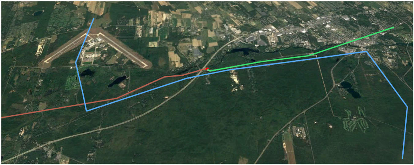
Importe dados do trajeto da linha central vindos de formatos compatíveis da SES, de DXF (por meio do SESConverter) ou ainda diretamente de arquivos Keyhole Markup Language (KML).Especificação de dados de forma intuitiva e visual
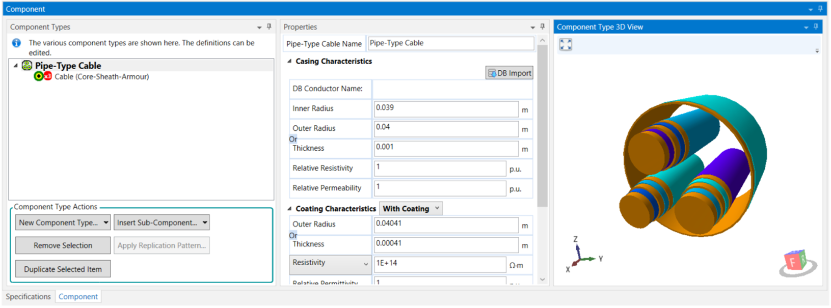
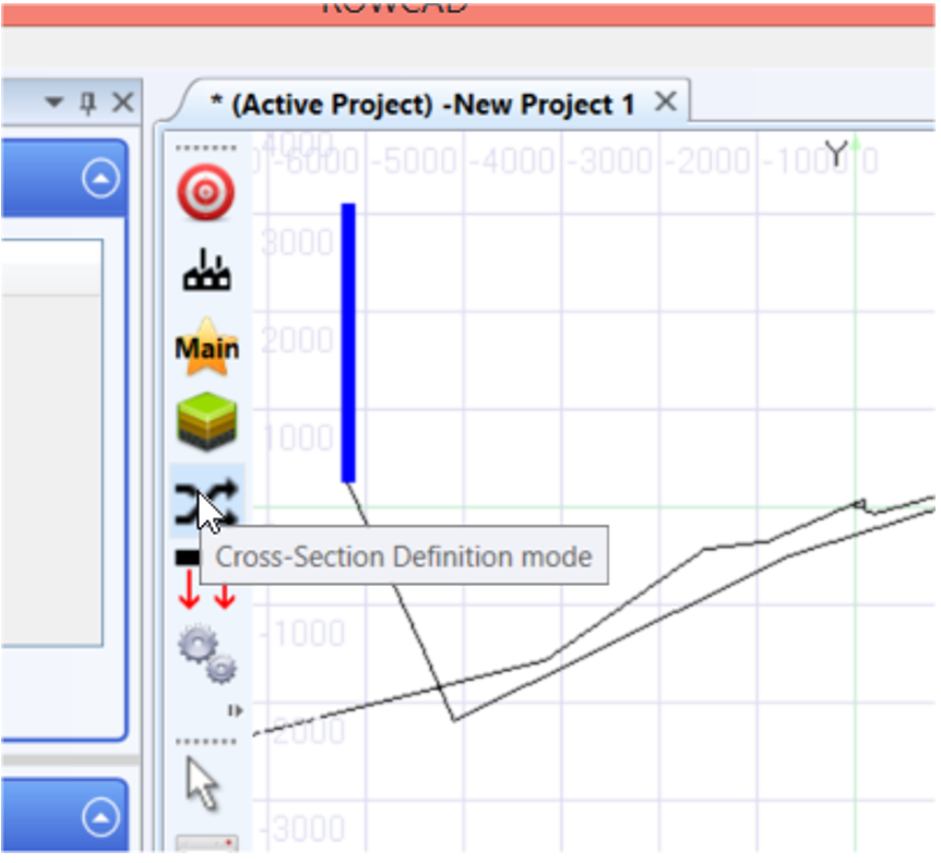
Defina graficamente as características dos condutores e os cortes transversais dos trajetos com SESCrossSection.
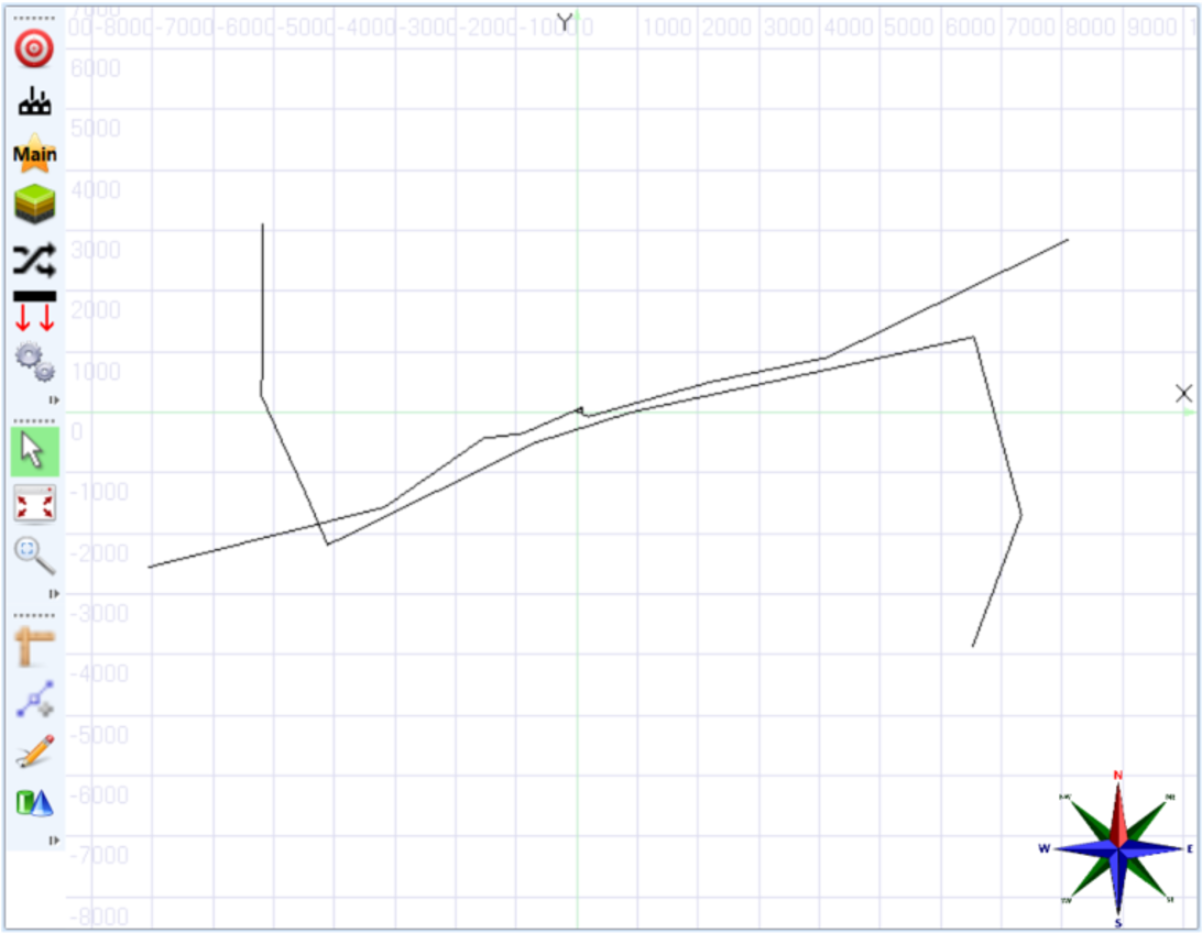
Atribua os cortes transversais, as regiões de solo e os parâmetros de circuito direto do visualizador do sistema gráfico.
A especificação por dados tabulares também está disponível, para se adaptar às suas preferências e às especificidades do seu projeto.
Defina modelos de solo, informação das fases e alimentação do sistema, ou ainda adicione anotações na visualização do seu modelo para se encontrar melhor nele.
Ferramentas auxiliares de desenho
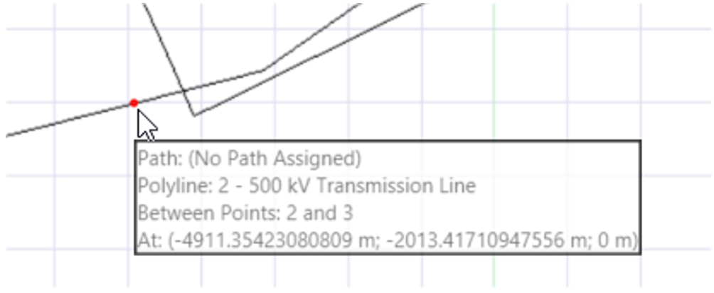
Use a ferramenta de bloqueio por proximidade para encontrar uma localização exata ao longo dos seus trajetos definidos:
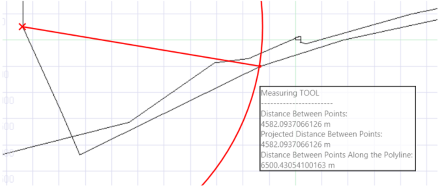
Meça o comprimento de uma linha reta ou a distância ao longo de polilinhas:
O modelo pode ser girado ou panoramizado, como preferir.
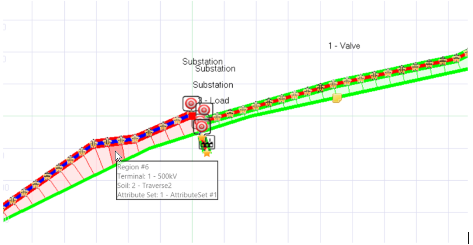
Por último, deixe o programa determinar as zonas de interferência por acoplamento indutivo para criar um modelo de circuito preciso:
Integração total ao Right-of-Way Pro
Importe informações de uma parte do sistema ou dele todo para criar um modelo de circuito e continuar seu estudo.
Uma estrutura de gerenciamento de projetos para o ROWCAD
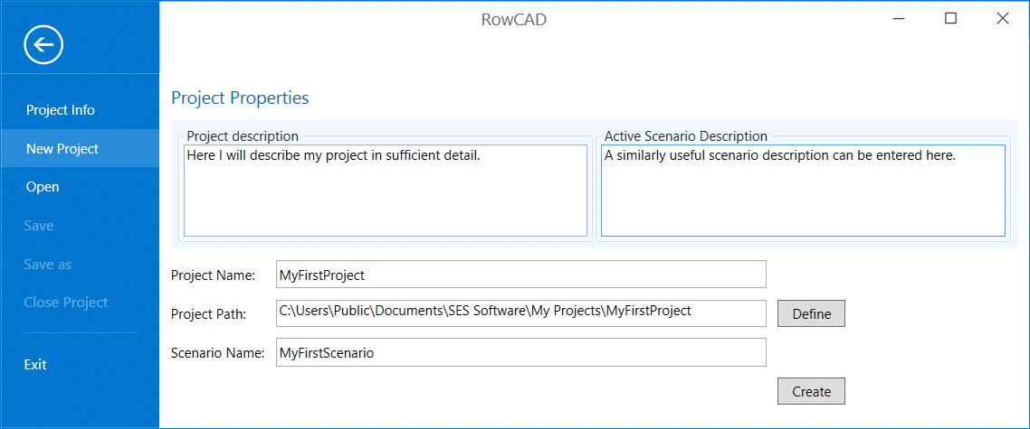
O ROWCAD tem uma estrutura "projeto com cenários", que é conveniente para gerenciar diversos modelos relacionados. Ele tem um formato de arquivo compacto e é integrado ao núcleo do módulo Right-of-Way.
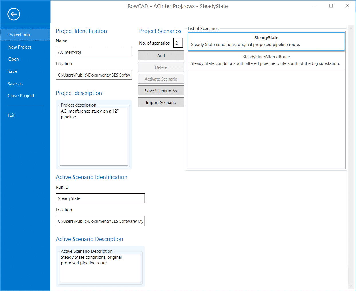
O projeto e os cenários são administrados na tela de informações do projeto:
Links dos projetos, cenários editados recentemente ou um conjunto de localização de pastas-padrão são mostrados.
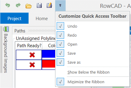
Uma vez que um cenário é criado, um menu tipo faixa de opções fica disponível. Antes, bem no canto superior esquerdo da tela, estão os botões de atalho para desfazer, refazer, abrir, salvar e salvar como.
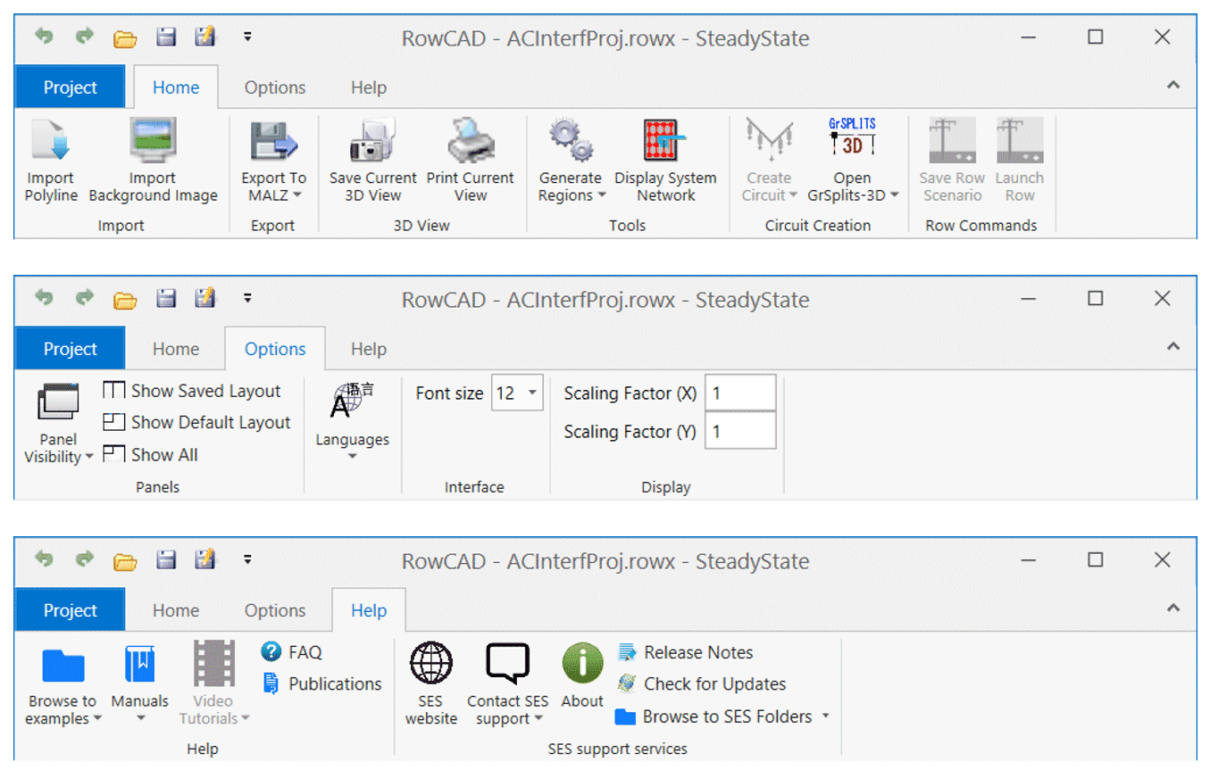
Depois, a faixa de opções oferece acesso a uma variedade de ferramentas sem precisar expandir os menus. Ela contém abas de início, opções e ajuda.
Ao mesmo tempo em que fornece uma interface gráfica intuitiva, ROWCAD é totalmente integrado ao Right-of-Way. Assim que todos os dados de entrada necessários são especificados e que o recurso de gerar regiões é ativado, um poderoso conjunto de botões fica disponível para criar circuitos, abrir o GRSPLITS-3D e salvar o cenário Row. Um botão para iniciar o Row fica disponível depois que a criação do circuito é concluída ou que o cenário é salvo no ROW.
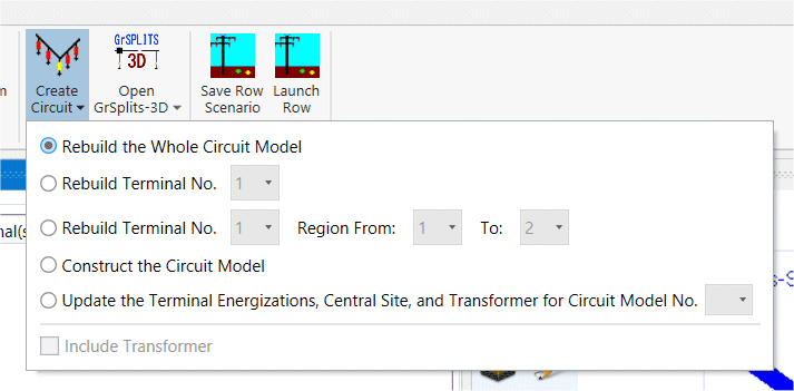
O botão de criar circuito irá criar automaticamente um arquivo de projeto ROW no mesmo nível de um arquivo de projeto do ROWCAD.
Ele inclui, ainda, as opções de criação de circuito que o ROW oferece.
Nesse ponto, você poderá especificar seu sistema inteiro diretamente no ROWCAD de forma compacta e completar a criação do circuito com menos ações, tudo isso mantendo uma estrutura de pastas organizada e consistente, sem esforço adicional.
Definição completa do modelo no ROWCAD
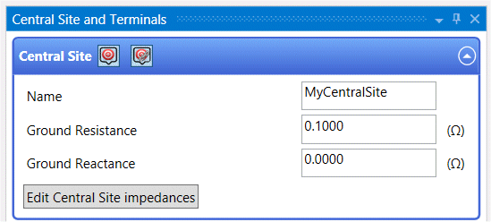
Definição das impedâncias do local central
A resistência e a reatância do aterramento do local central podem ser definidas diretamente no ROWCAD.
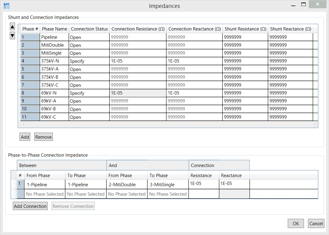
O botão para editar as impedâncias do local central abre uma tela para que sejam especificadas as impedâncias de ligação entre cada fase individual e o aterramento, a impedância shunt e as ligações fase‑fase no local central.
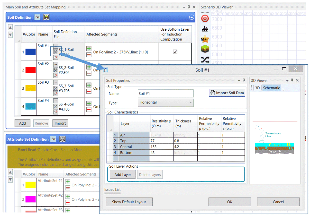
Tela de escolha do modelo de solo
Os modelos de solo são armazenados diretamente no cenário do ROWCAD, que mantém os arquivos bem organizados e transportáveis.
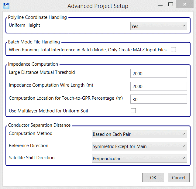
Um botão de configurações avançadas acessa a tela que permite o ajuste das configurações.
Ok/Cancelar em todas as janelas
O ROWCAD com frequência envolve muitas telas e janelas secundárias para completar a entrada de dados, e agora todas elas estão equipadas com botões de confirmar e cancelar alterações.
Ferramentas de desenho novas e melhoradas
Ferramentas relacionadas a entidades
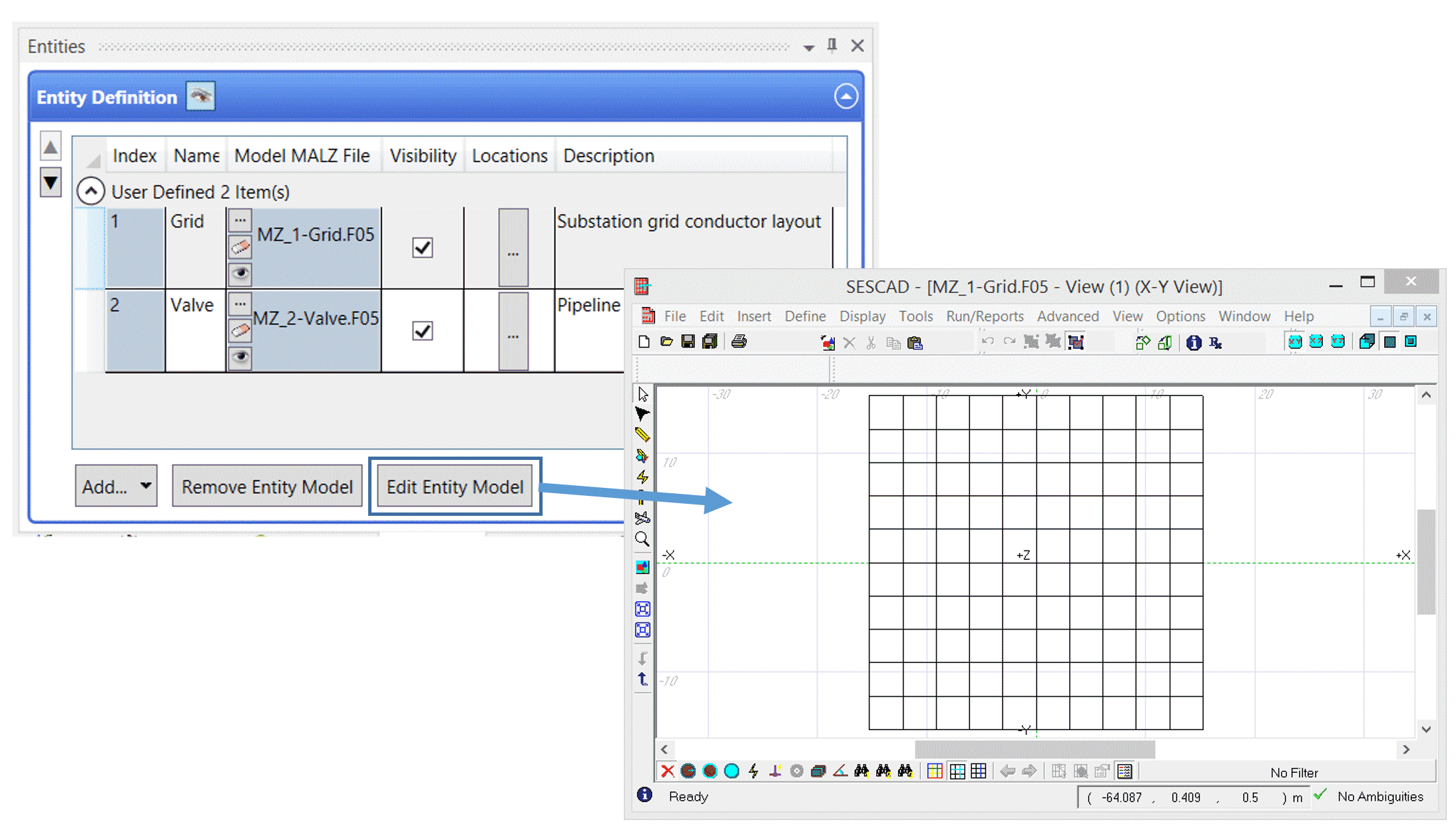
Entidades no ROWCAD podem ser usadas para definir notas, assim como pontos de observação e configurações de condutores a serem incorporados no arquivo-modelo do MALZ com o intuito de realizar a análise de interferência total (interferências CA por acoplamentos indutivo, capacitivo e condutivo).
Elas podem ser definidas e editadas por meio da interface do SESCAD aberta diretamente do ROWCAD. É só salvar sua criação antes de fechar o SESCAD que a entidade será definida.
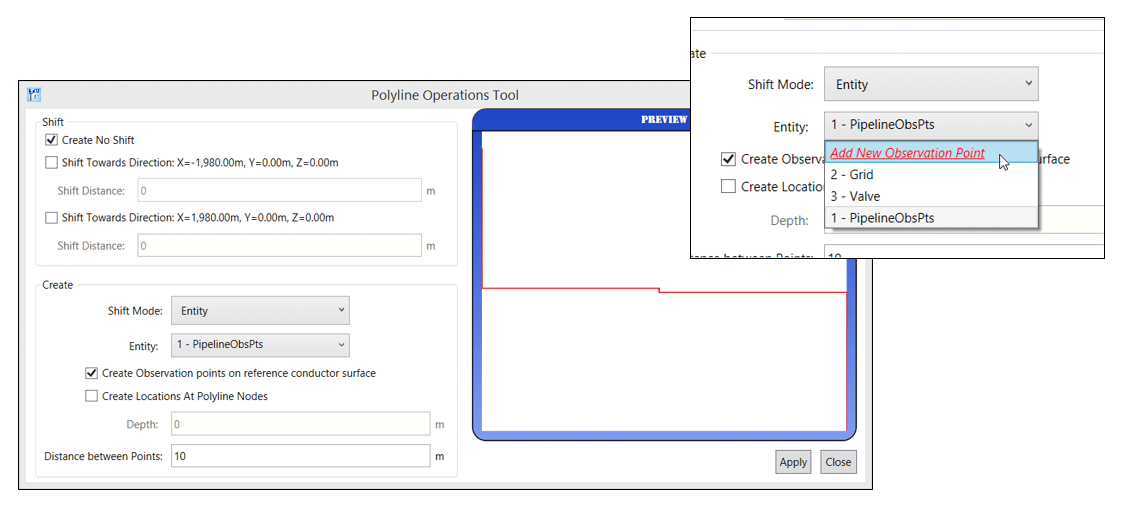
A ferramenta de operações de polilinhas tem a capacidade de definir pontos de observação ao longo de uma polilinha com uma separação de pontos personalizada e pontos de observação na superfície do condutor de referência.
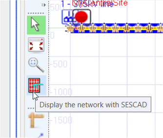
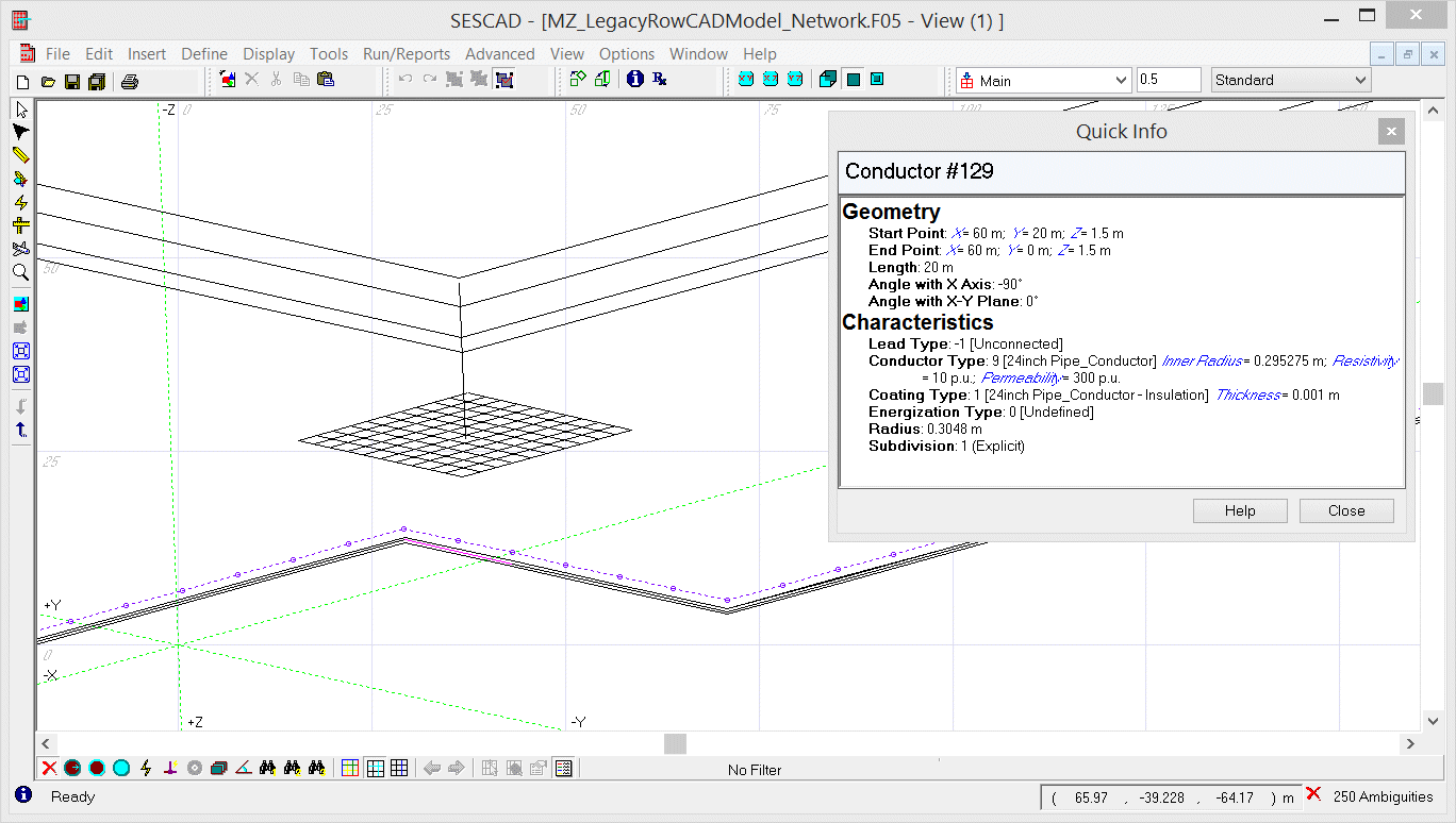
O ROWCAD agora está equipado com a ferramenta de mostrar a rede no SESCAD logo na barra de ferramentas do visualizador, muito parecido com a de "desenhar rede" do ROW.
Esse visualizador é substancialmente mais informativo, pois exibe não apenas o sistema no que diz respeito às polilinhas (incluindo tipos detalhados de condutores), mas também a correta localização das entidades, além dos modelos simplificados de torres, onde pontos para indicar torres são vistos ao longo da polilinha.
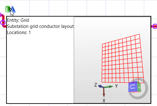
As entidades também podem ser selecionadas e movidas com o cursor. Além disso, uma visualização 3D da entidade é exibida se o cursor passar sobre a localização dela.
Todas essas ferramentas permitem o desenho completo e eficiente de um modelo MALZ de interferência por acoplamento condutivo diretamente no ROWCAD.
Ferramentas relacionadas a polilinhas e cortes transversais
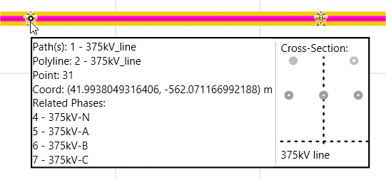
O ROWCAD agora inclui a exibição melhorada das propriedades de cortes transversais atribuídos a porções de uma polilinha. A informação de contexto mostrada quando o cursor passa sobre uma polilinha apresenta as fases associadas a ela e uma vista 2D do corte transversal.
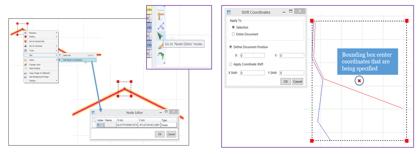
Nós de polilinhas podem ser editados direto no visualizador, por meio do novo modo de edição de nós, acessível na barra de ferramentas. Todo o sistema ou parte dele pode ser deslocado para qualquer lugar.
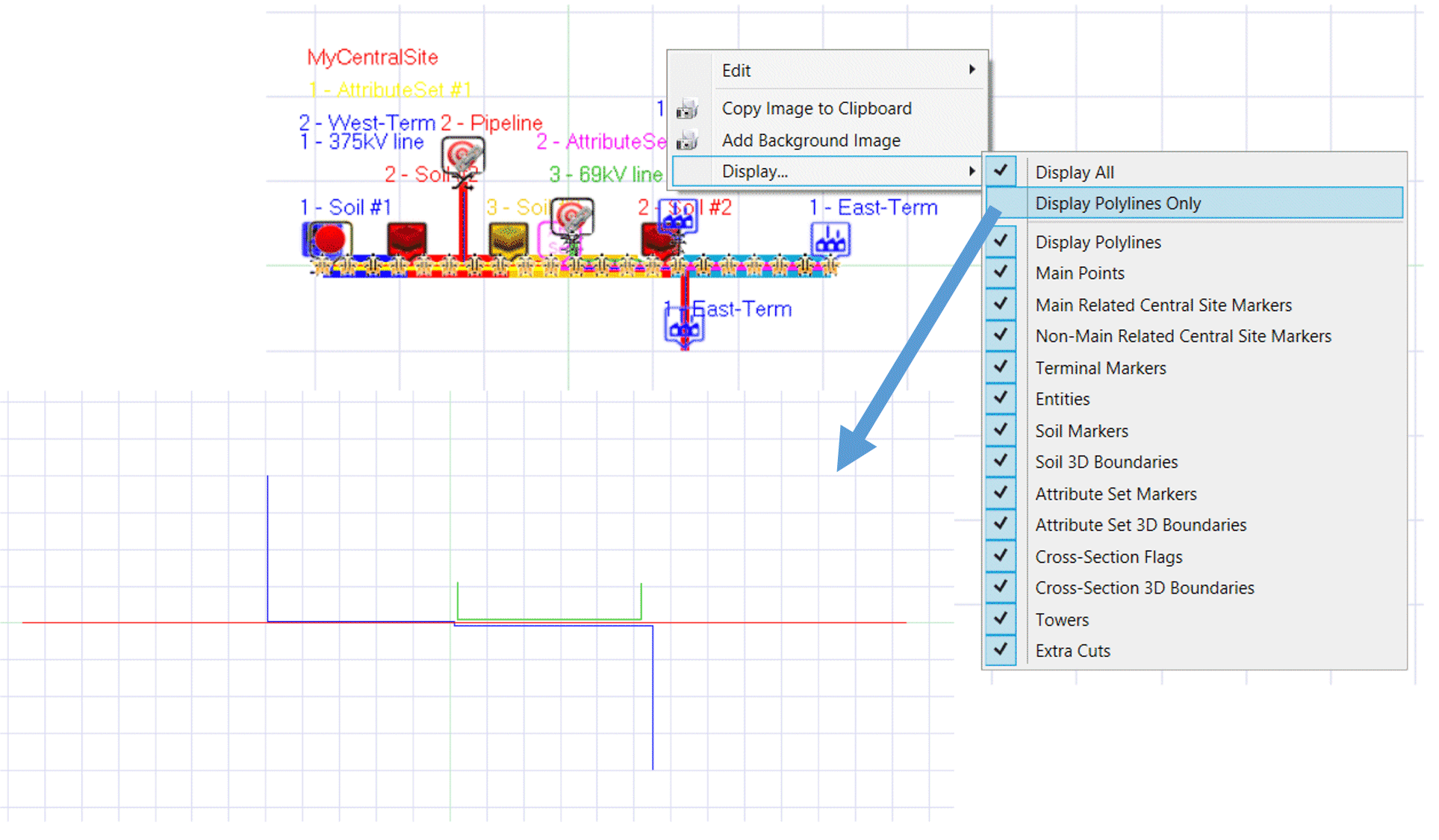
O visualizador do ROWCAD tem atalhos para ativar e desativar todo o feedback visual referente às atribuições feitas nas polilinhas (Pontos principais, Local central e marcadores de pontos de mapeamento do local central, Marcadores de solo etc.) e para reativar tudo. É só clicar com o botão direito do mouse no visualizador e selecionar para mostrar só as polilinhas ou mostrar tudo.
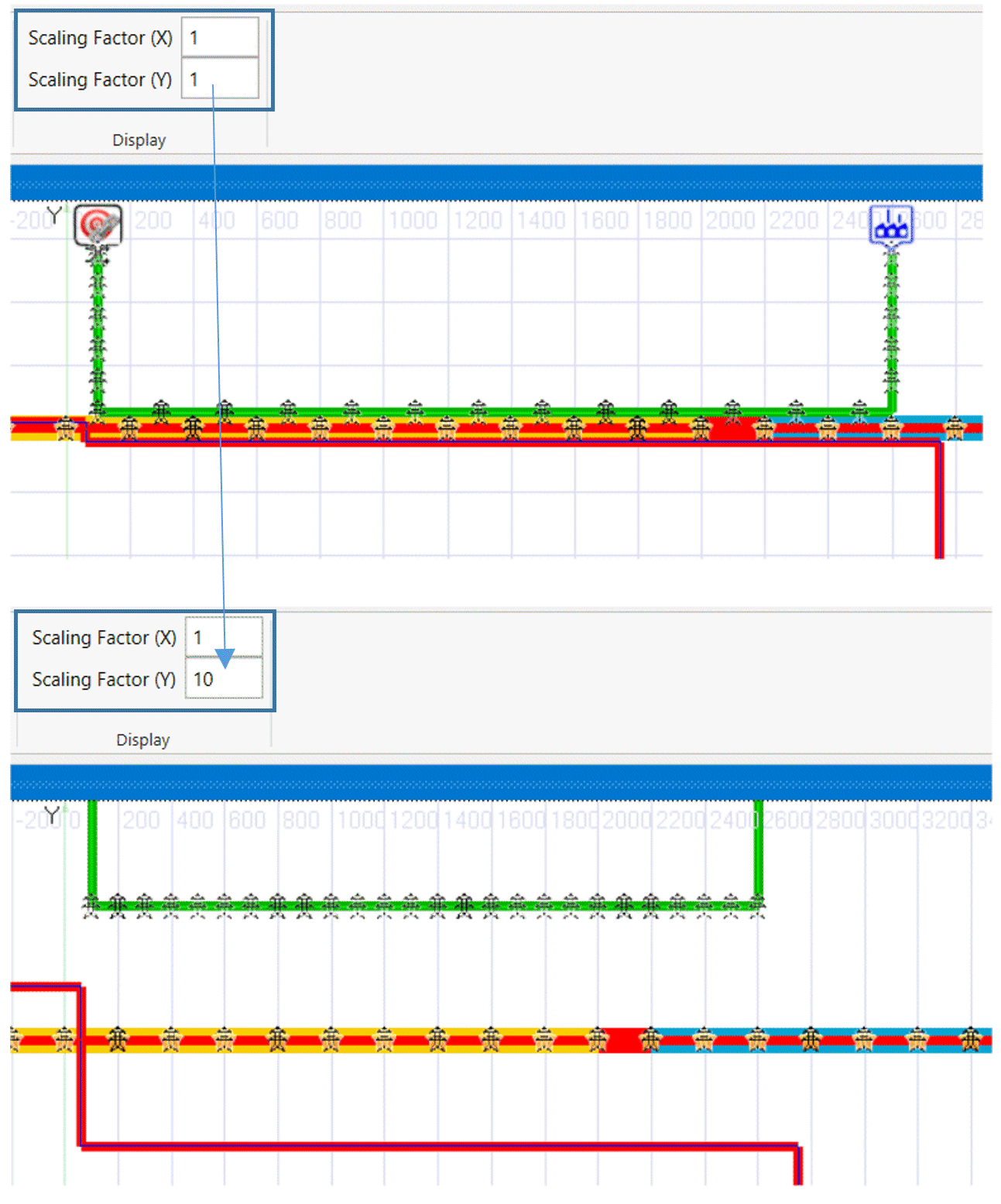
Fatores de escala independentes podem ser definidos para os eixos X e Y, e para personalizar a visão do sistema.
Validação melhorada dos dados de entrada
Um ponto crucial no desenho de modelos de interferências CA é a grande quantidade de dados que precisam ser incorporados no modelo. Por isso, a ferramenta que lista os problemas restantes se tornou central na hora de encontrar erros ou omissões nos dados de entrada. Muitas validações úteis foram adicionadas ao ROWCAD para minimizá-los. Eles são rastreados de forma dinâmica, sendo essa lista constantemente atualizada para garantir que esses problemas sejam tratados o mais rápido possível.


